High Field ESR with Quasi-Optics and Philippe Goy's AB VNA
Our QO approach to ESR measurements can be combined with Philippe Goy's AB Vector Network Analyser to provide powerful and very wideband ESR spectrometers:
Pictured below is one supplied to Vladislav Kateav at the Leibniz Institute for Solid State and Materials Research in Dresden
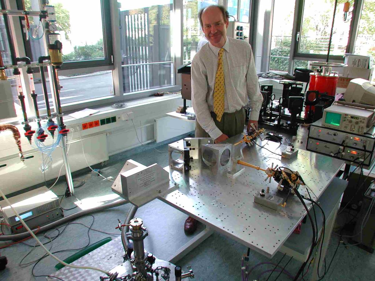
The QO circuit is a simple one – Source power is formed into a Gaussian beam by one corrugated feed horn and passes through a wire polarizing Grid before being refocused by a zero gain frequency-independent pair of mirrors onto the top of the HE11 probe. The returning Inductive mode orthogonally polarized beam also passes through the two mirrors train, but this time is reflected by the grid into the detector feed horn.
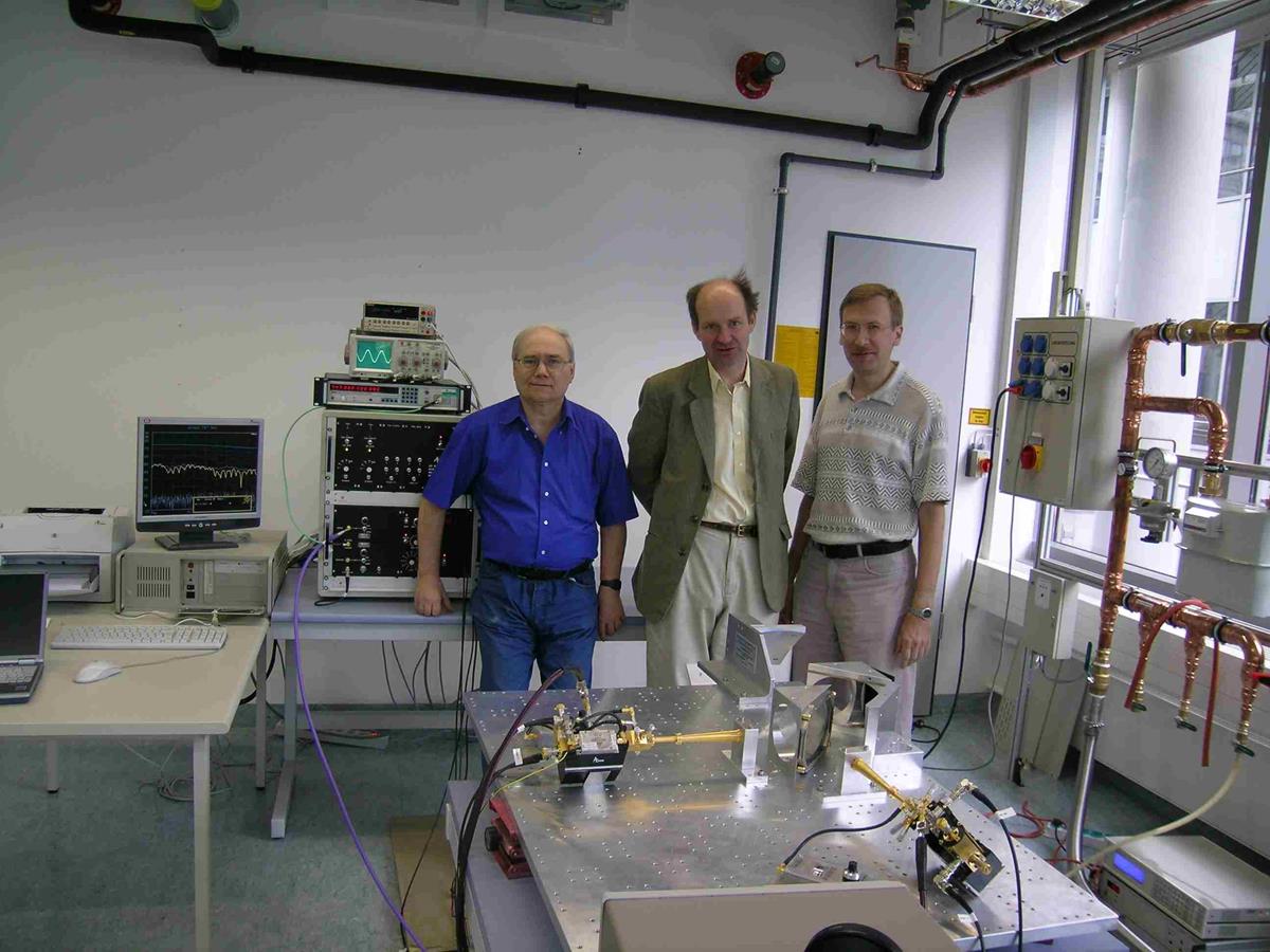
Behind the Quasi-optics table are Philippe Goy, Richard Wylde and Vladislav Kateav
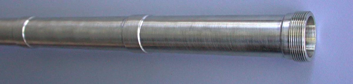
Here are small photos of the sample and QO ends of the HE11 probe respectively.
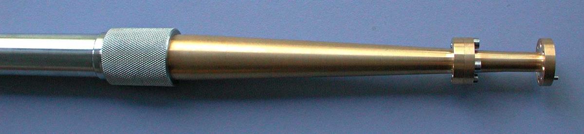
The main part of the probe is made from German Silver – a balance between machinability and thermal conductivity (you want the former to be good and the latter poor).
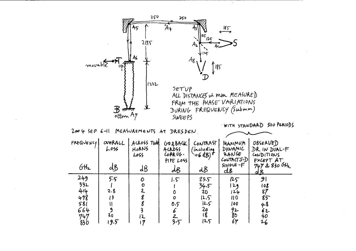
Losses and Inductive mode isolation in the QO/HE11 probe subsystem were measured by Philippe and presented in the table below. Our design was optimised for the 350 GHz region. A metal reflector was placed at the sample chamber position, to provide 100% reflection. A grid, giving -6dB worth of coupling, simulated the Inductive mode for these tests.
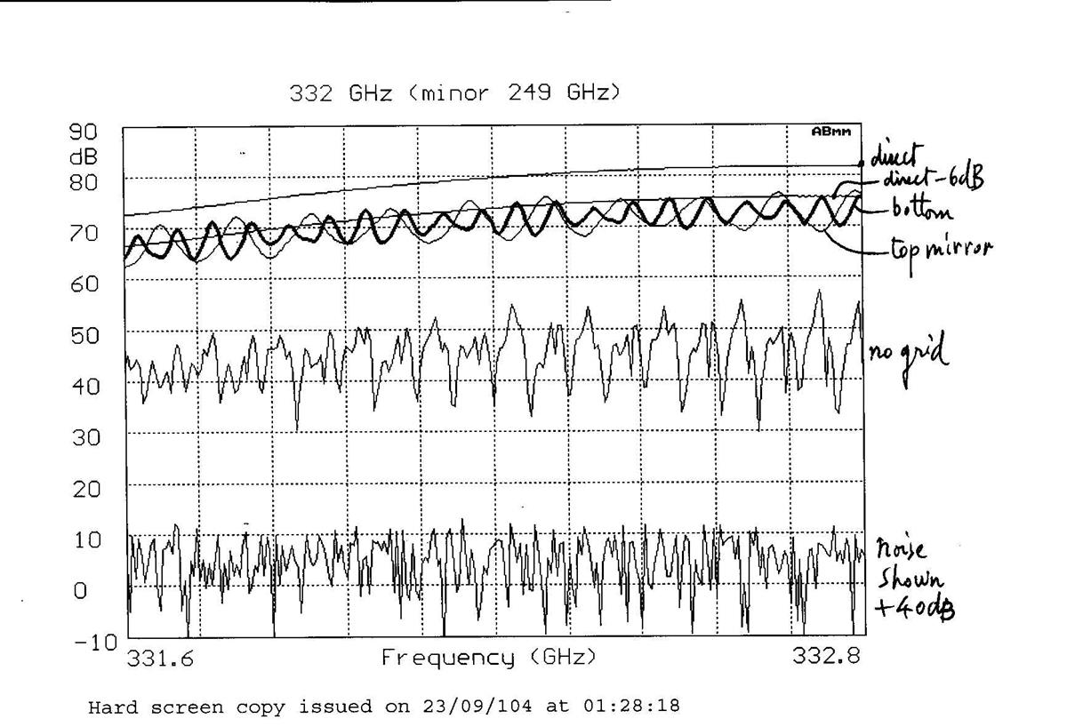
The loss was measured against a source/detector flange calibration. The standing wave are a result of reflections between the sample holder position and the source waveguide (See comment lower down). By removing the Grid (“no grid” above), the Inductive mode isolation can be determined. The lowest line gives the Noise floor – in this case >70 dB below the signal
Note that the loss from source horn flange, through the QO and down and back up the HE11 probe a,d back though the QO to the detect horn flange. There is little difference when one adds a metal reflector at the top of the HE11 probe, indicating that it the probe is close to being lossless (as measurements of HE11 transport lines for Plasma-Fusion Gyrotron heating would suggest – with powers >1MWpassing though albeit overmoded guide, melting would occur unless loss were only a fraction of a dB per Metre).
It is quite surprising over how wide a band measurements are possible – well outside the traditional single moded region. Performance dips as the HE11 slots become close to a half wavelength but good performance returns as the slot depth heads towards ¾ wavelength, as the table below shows.
Contact Richard Wylde for more details.
Comments: Looking at the plot at 332 GHz. There are about 19.5 standing waves present across 1.2 GHz So that gives a period of 60 MHz, or a round trip distance of 4.8M. The total optical length is about 2.35M, from sample holder to horn flange.