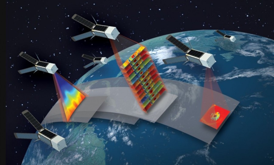
TK designs the antenna for TROPICS, a NASA-Funded MIT CubeSat radiometer mission
TK has been engaged in the electromagnetic and mechanical design and manufacture of the antenna of TROPICS, a NASA mission using a set of 3U CubeSats with a radiometer payload to observe tropical storms from space.To quote the mission specification:
"The Time-Resolved Observations of Precipitation structure and storm Intensity with a Constellation of Smallsats (TROPICS) mission will provide rapid-refresh microwave measurements over the tropics that can be used to observe the thermodynamics of the troposphere and precipitation structure for storm systems at the mesoscale and synoptic scale over the entire storm lifecycle. TROPICS comprises a constellation of CubeSats in three low-Earth orbital planes. Each CubeSat will host a high-performance radiometer scanning across the satellite track at 30 RPM to provide temperature profiles using seven channels near the 118.75 GHz oxygen absorption line, water vapor profiles using 3 channels near the 183 GHz water vapor absorption line, imagery in a single channel near 90 GHz for precipitation measurements, and a single channel at 206 GHz for cloud ice measurements."
The antenna needs to cover three principal bands into a single beam - with the following 3 dB full beam-widths in degrees
- 88.15-94.15 GHz ≤3.0 at 92 GHz
- 114.5 to 118.75 GHz ≤2.4 at 118 GHz
- 183.3 to 205 GHz ≤1.5 at 183 GHz
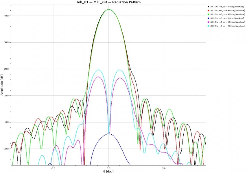
Predicted patterns at 183 GHz from the offset parabolic feed show good beam performance and X-polar below -20dB
A dual-depth corrugated horn covers the bottom two bands, and a single corrugated horn the top band, combined by a free standing wire grid:
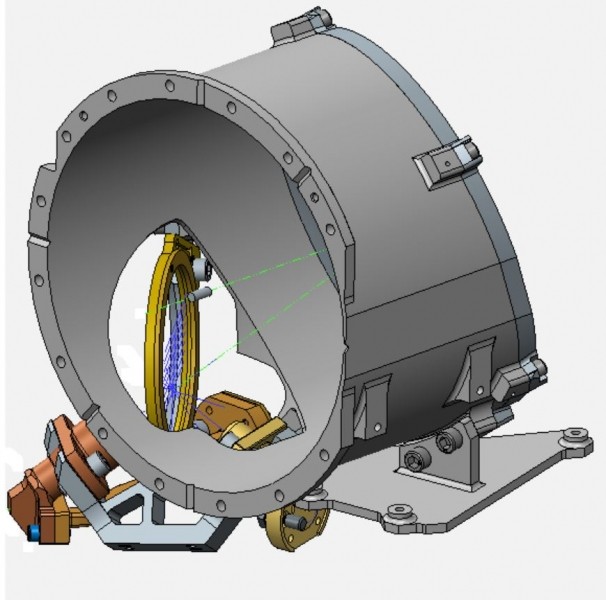
The CREO CAD image shows the two corrugated horns aimed at the polarizing grid
Giving the very small size of the spinning radiometer (basically 100mm cubed), some very compact and yet low sidelobe corrugated horns were neeed: These were designed by Dr Graham Smith of St. Andrews optimising a set of HE1n modes to give a very Gaussian beam in a very short horn. The waveguide structure, refined with HFSS analysis by Dr Soe Min Tun, has quite an unusual structure - with a 140 degree bend to allow the feed horn's exit aperture to sit in the corner of the cube.
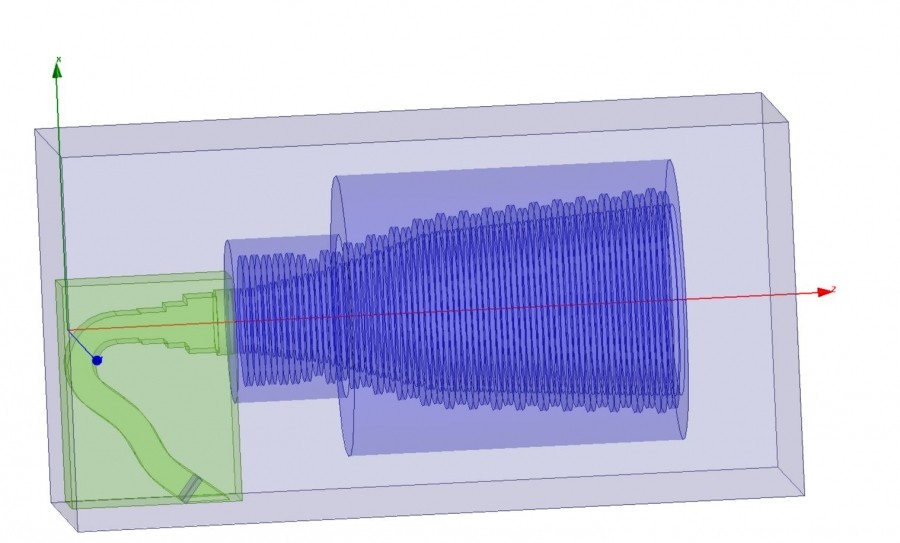
The Low frequency dual-depth horn with waveguide bend, undergoing HFSS analysis
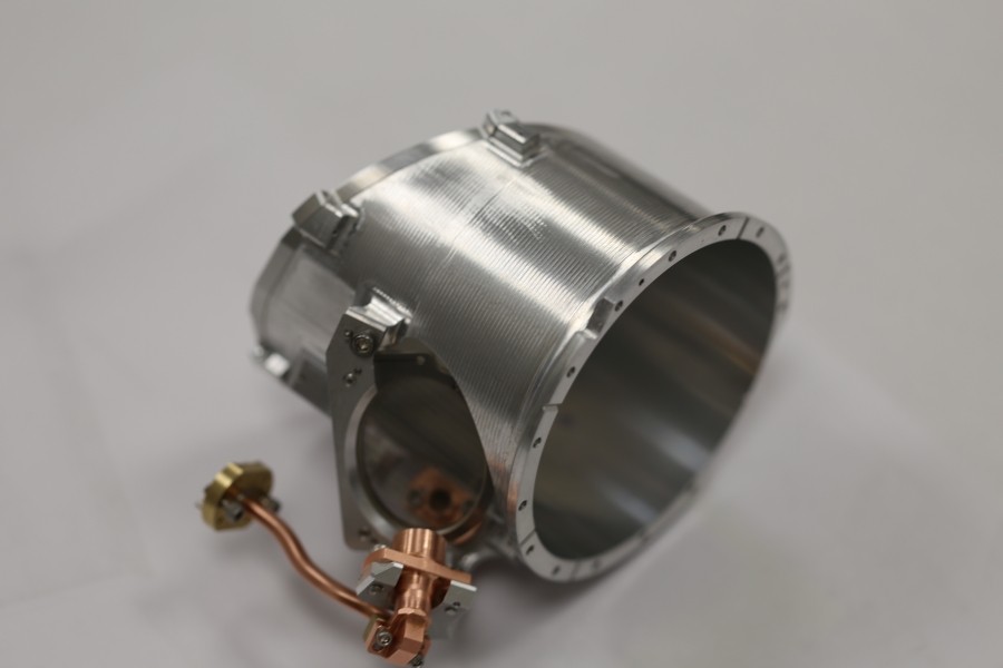
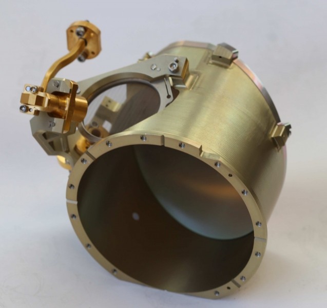
The horns are electroformed copper, and attached to an aluminium shroud structure, which also houses the main offset parabolic mirror.
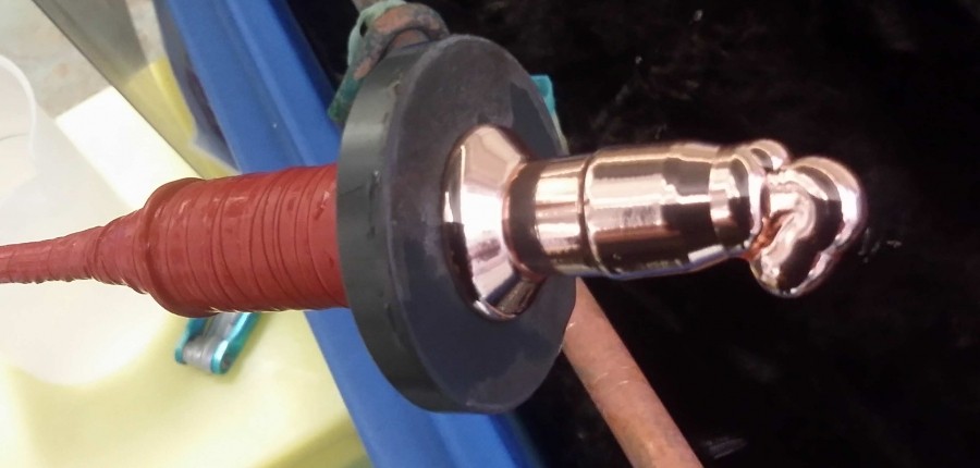
Low frequency horn extracted from TK's plating bath, showing the odd "hook" waveguide
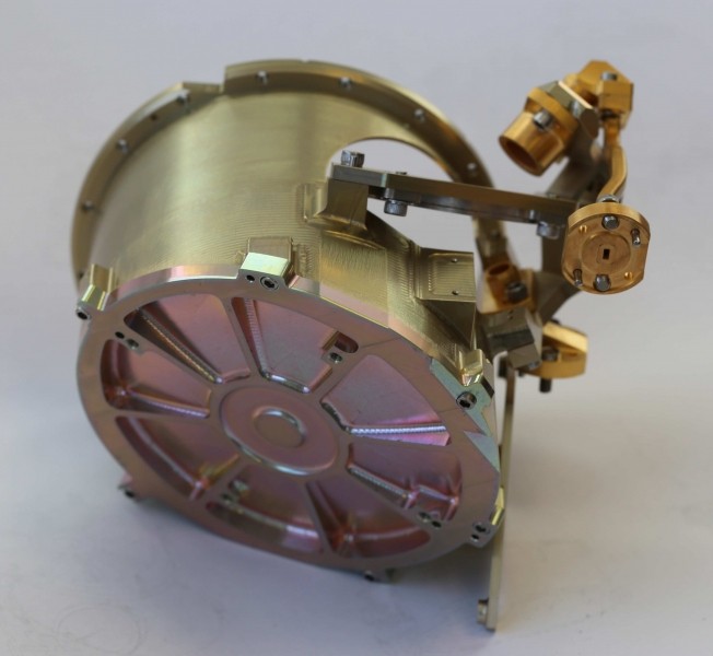
The first "Risk Reduction Unit", RRU, is shown below, and is currently (late Dec 2017) undergoing electromagnetic testing:
Pre- surface treatment, showing unplated Cu and Al......
and after treatment
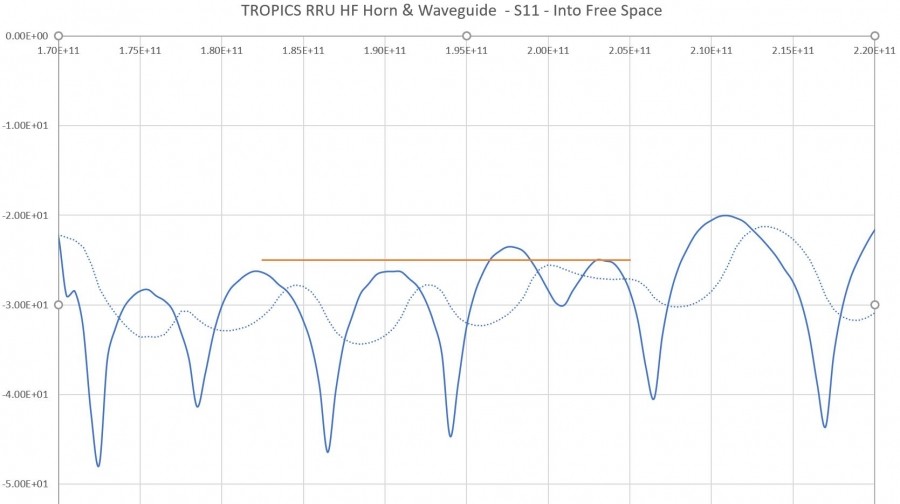
The return loss of the high frequency horn - kindly measured on a VNA in the Astrophysics Instrumentation Group in Cardiff - is shown below